Replacing the SD Card Reader on a Raspberry Pi for 2.50 Euros
So what should I do? Clearly I could reorder the SD card reader at one of the distributors, but it’s going to be expensive, and, more importantly, it’s going to be the same crappy reader that will most likely break again (unless your learn from your errors, which I rarely do). But the spare part itself is ridiculously expensive, some 6 Euros + shipping just for a spare part.

Note that for simplicity, the new reader will ignore the read-only switch of the SD Card. The respective pads on the PCB will simply be shorted (If you want to go the extra mile, you can of course fix this properly). Also, not every card reader on the market is the same. Check how your reader is connected, and which pins serve which purpose.
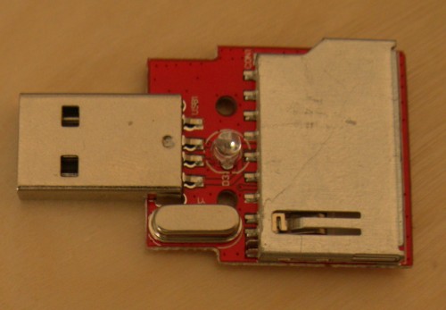
Still with me? Well, luckily there is a cheap USB key card reader (affilate link) available which I aquired at at Amazon.de at 2.50 Euros, including shipping. Yes, it’s sad to deconstruct a completely working USB key because it’s cheaper than a spare part, but on the upside you gain a USB connector, an LED and a quartz crystal and a controller as free spare parts for your next projects.
Required Parts and Tools
- USB Card reader
- Tin-solder
- Enamelled Wire
- Soldering iron
- Desoldering wick
- Desoldering pump
- Opt: Volt meter
- Opt: Pliers
- Opt: Wire
- Opt: Hot-melt gun
The process
Unsolder new Card Reader from USB Reader
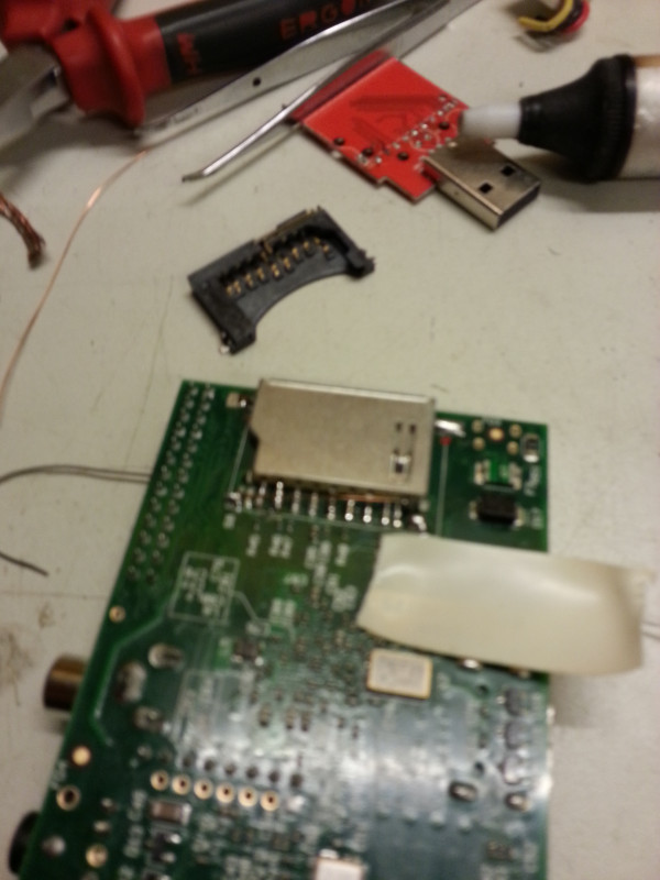
Open the USB keys’ plastic housing by inserting a screw driver into the card slot and turn it by 90 degrees. Once you have gotten hold of the PCB, unsolder the LED and the quartz crystal first – they are in the way. Finally, unsolder the reader pin by pin. Be careful: the pins loosen easily, and if they fall off, you will have to replace them with a piece of wire, which makes the process more difficult.
Unsolder old Card Reader from RPi
Using pliers to cut off the connectors close to the reader gave good results. Use desoldering techniques for proper separation if still required. The more pin wire is left on the board, the easier the resoldering will be.
Resolder new Card Reader to RPi
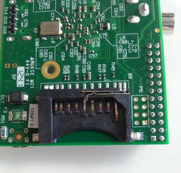
The SD Card Reader on the Pi is connected via SPI. The general mapping of an SD Card to the SPI can be deduced from pin mapping at Wikipedia. The mapping of the pins remains the same with our chosen reader. However, there are four more pins as you can see from the close up on the right.
As you can see, there are thirteen pins, but there are only nine connectors on the card. We need extra pins for detecting if a card is actually inserted (located on the pins to the right) and another to check if the card is notched (i.e. write-protected, located on the left).
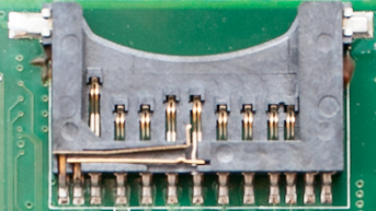
Now we need to map the pin layouts to the new card reader. On our case, the pin mappings are identical. However, the new reader only has eleven pins, but we will be fine – just find the two additional data pins, which set themselves apart from the rest of the pins in height — both are located on the right hand side of the new reader (see the top most picture). The left one is the one you want to solder to to any of the ground pins using the the enamelled wire — we chose the second from the left. Finally, shorten the two left-most contacts pins on the PCB to signal the PI that the card is always on read-write (again, you can easily fix this yourself if you really want your OS to reside on a read-only card).
The result

Making it rock-solid
Use some solder to fixiate the reader on the sides, even though the card reader might not have extra spots to hold the solder tin. It will most likely still work. If you want to make sure your reader is really well-tied to the PCB, use a hot-melt gun and put some glue onto the new wiring (check if it works first, there is no going back!), as well as on the sides.
Credits
The project was suggested by and conducted with the invaluable help of @d3rp3t3r.